Posted 2021/7/21
A CRT TV with a Secret
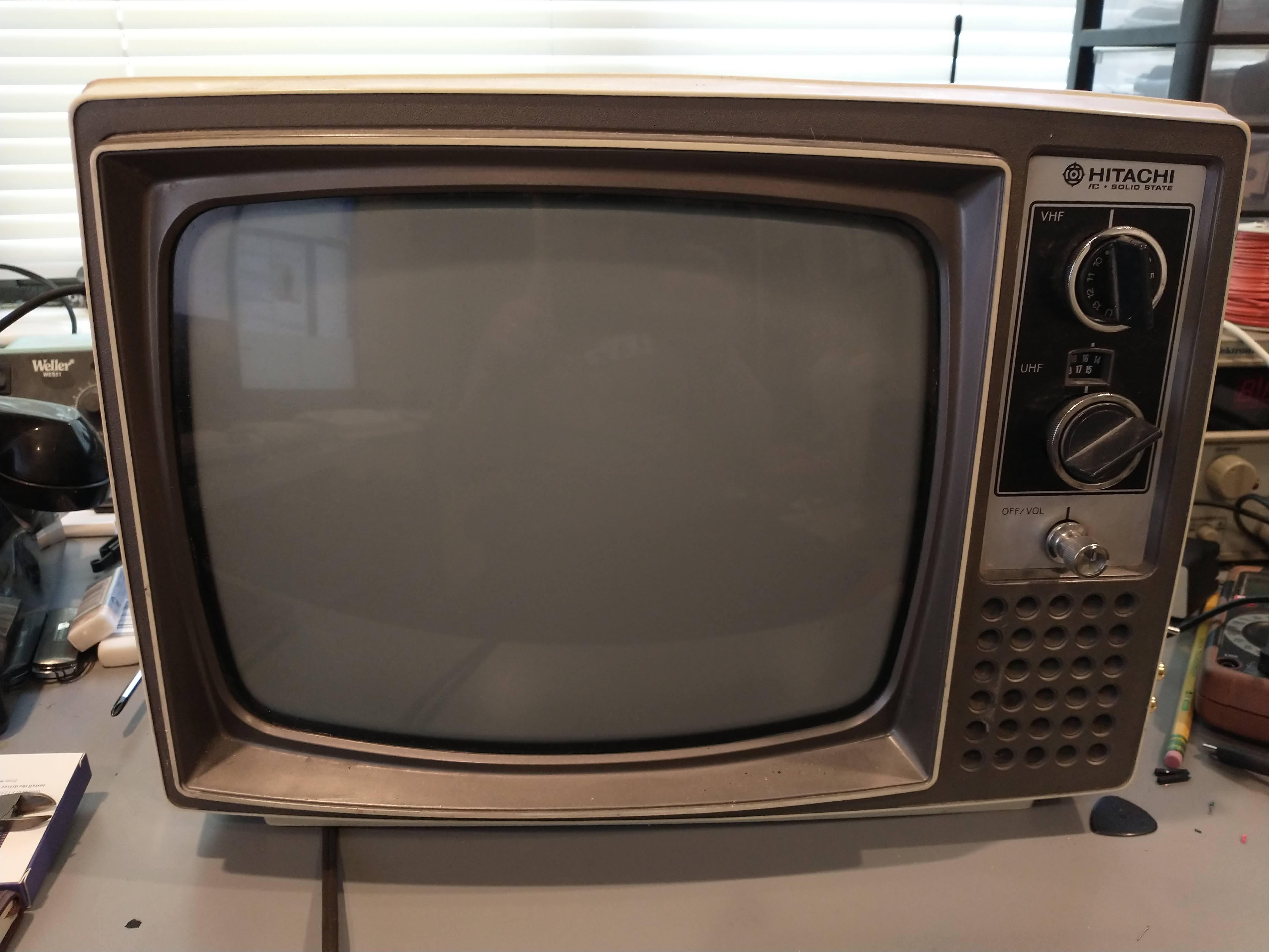
A few years ago, I found a neat-looking old TV in a thrift store. It’s a Hitachi P-05, a small black-and-white unit:
When I got it home and started poking around, I found two sets of inputs on the back of the TV:
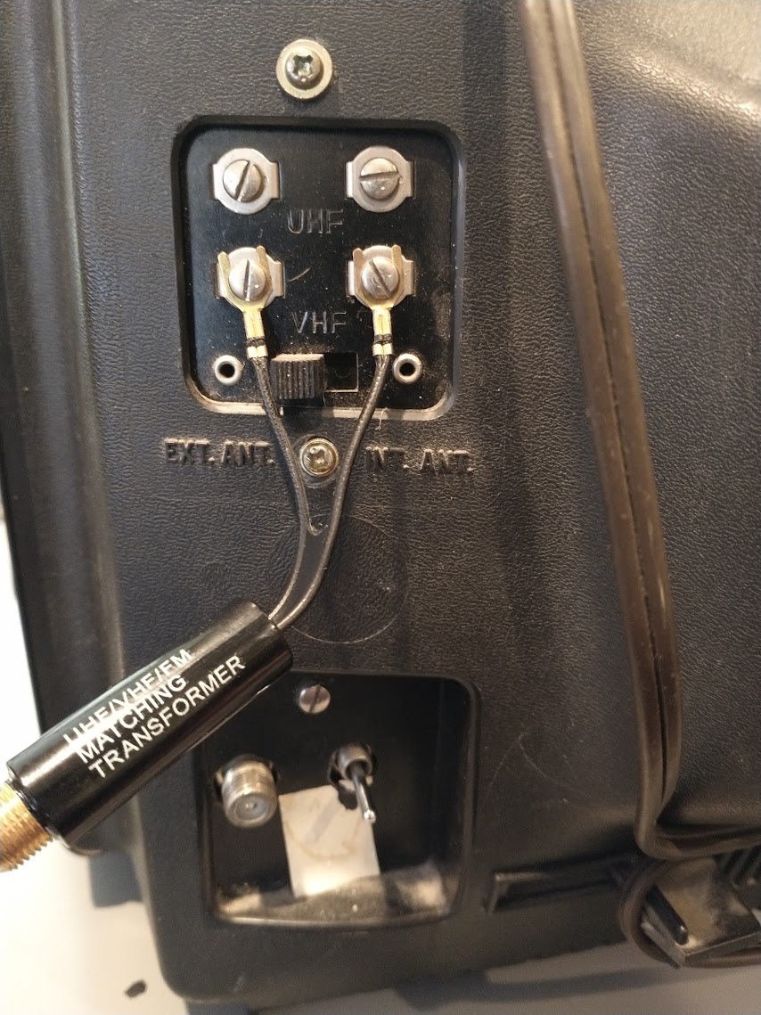
There were screw terminals for external VHF and UHF antennas, but there was also a terminal for an F-type connection, as you’d find on a cable box or a more recent TV antenna. Next to the F-type terminal was an unlabeled toggle switch.
However, when I connected an RF modulator to that input, I couldn’t get any video. Running the signal through a “pigtail” transformer attached to the VHF screw terminals worked fine, so I knew the TV worked, but I couldn’t figure out what this input was for. I decided to open the TV up and see what was back there:
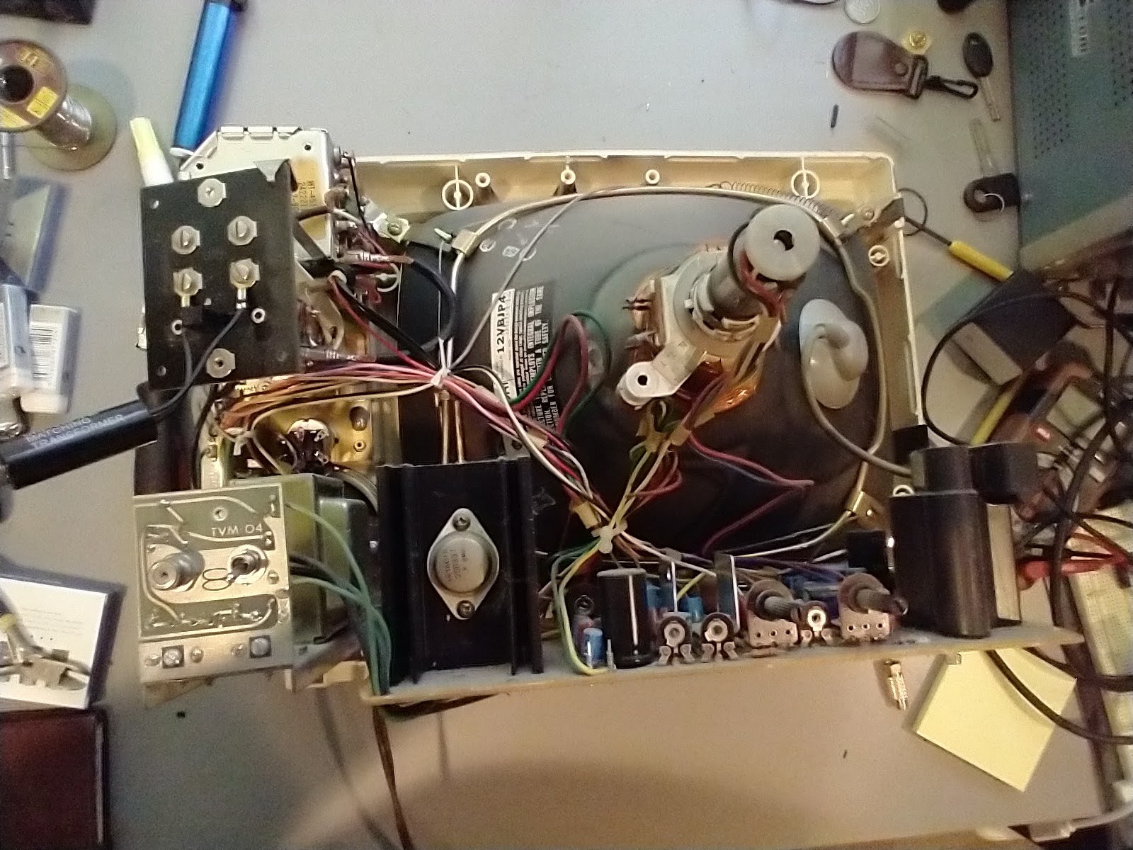
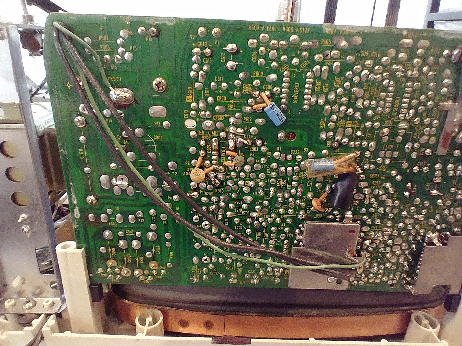
I found that it was a small, separate PCB which looked completely different from the main board:
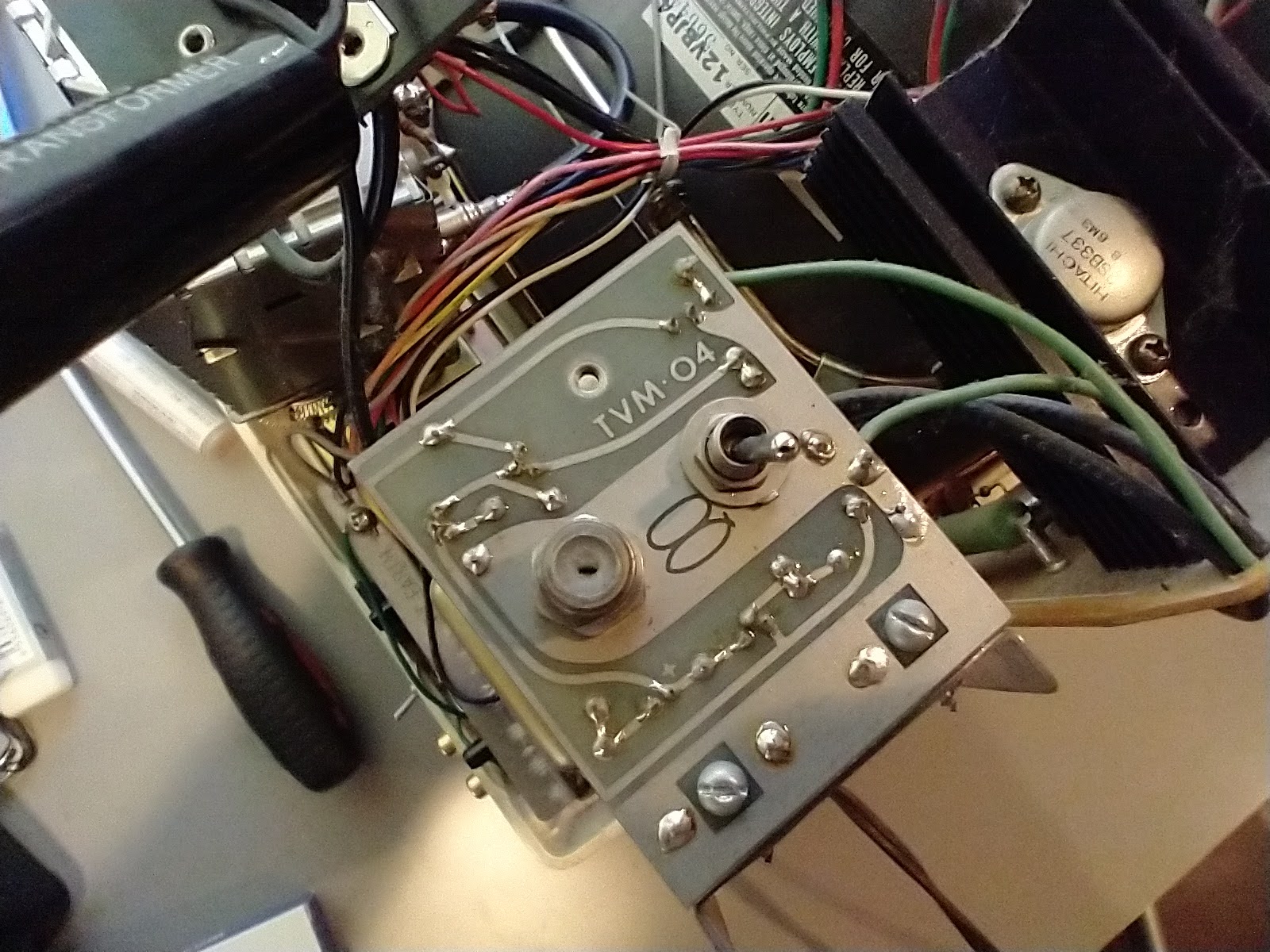
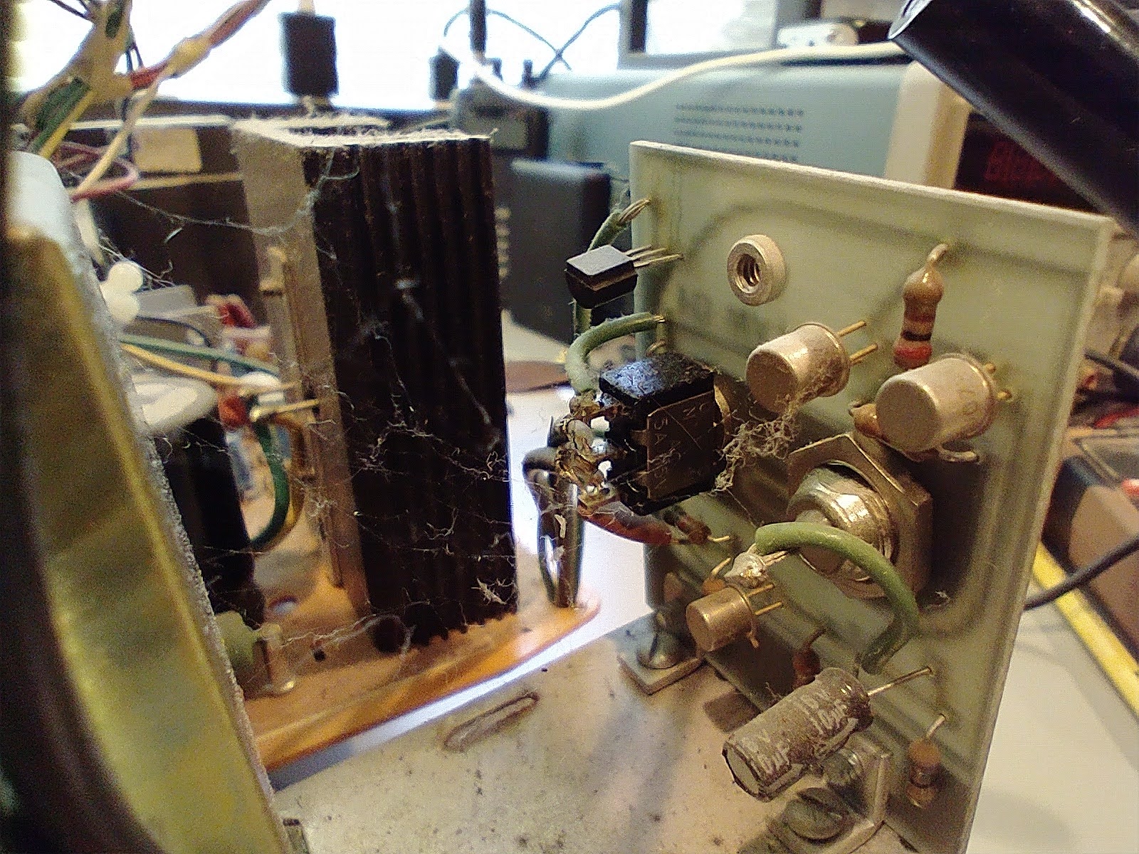
Tracing the wires from that board to the main board, it was connected directly to a shielded component which I felt pretty confident was some part of the video system:
I did some web searching and managed to come up with a match: a few volumes of Byte Magazine back in the 70s mentioned a “Pickes and Trout TVM-04” adapter for connecting your computer to a TV. Specifically, page 131 of the May 1978 Byte (Vol 3 No 5, currently available at this link) describe how to install the TVM-04 in a Hitachi TV set, including pictures which match my own set perfectly:
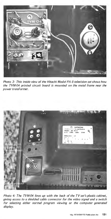
From the article:
The TVM-04 is $20 from Pickles and Trout, POB 1206, Goleta CA 93018.
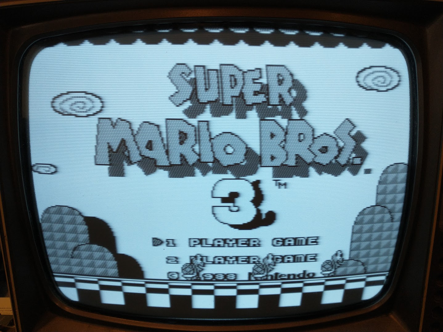
The magazine describes it as a “direct video entry” board, so I went to the local electronics shop and got an RCA to F-type adapter, plugged in a cheap NES clone that outputs plain composite video, and flipped the switch. Sure enough, it worked, and it looked way better than through an RF modulator!
The only problem was that it didn’t include audio, only video. So after looking around inside the case, I hacked together a solution:
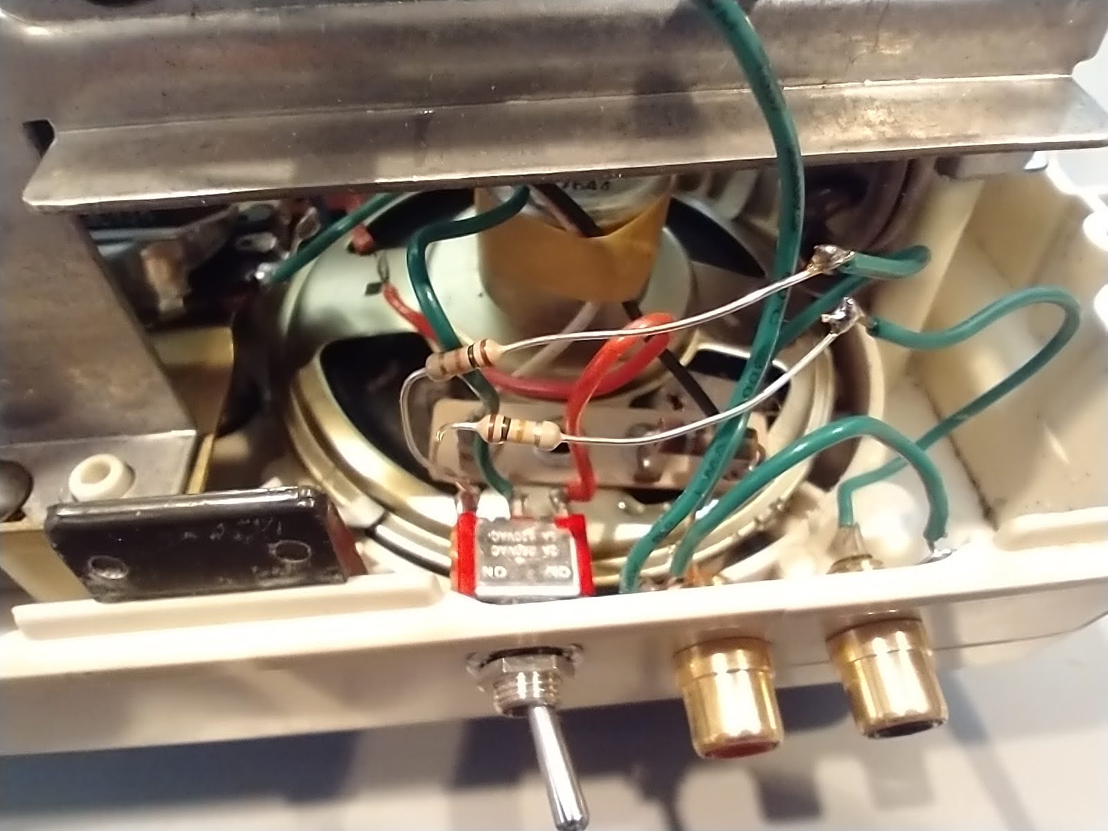
I found the input side of the volume potentiometer, then de-soldered the wire going into that pin. I extended that wire (the red wire in the foreground) to one of the inputs of a single-pole double-throw switch. I connected the output of the switch to the volume pot, then connected the other switch input to a pair of RCA jacks. Since the TV is mono-only, I just use a pair of resistors to “merge” the left and right channels.
                           (switch)
TV audio >-----------------o

                               _---o---------> volume pot input
RCA left >--/\/\/\---+     _---
                     |-----o
RCA right >--/\/\/\--+
I think it looks pretty good when it’s all buttoned up, and the volume knob works for my RCA input:
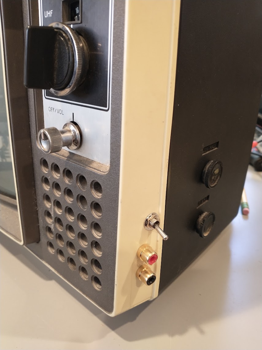
If I flip the audio switch and the TVM-04 switch off, the TV operates as it originally did: it outputs whatever comes in from the antenna inputs, so I could for instance hook up an old VCR. If I flip both switches, it displays composite video and plays RCA audio.
Based on the articles I read about the TVM-04, this was almost certainly used as a monitor by an early computer hobbyist. I picked it up in Albuquerque, so perhaps it was a Sandia Labs employee experimenting with the new-fangled microcomputers after work.