Posted 2019/5/11
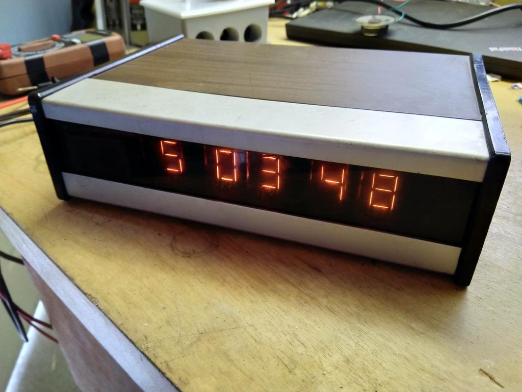
ES-112 Nixie Clock
I came across this clock at my favorite booth in a local flea market. The guy finds all sorts of weird electronic equipment and puts it up for sale at very reasonable prices. I think I paid $5.
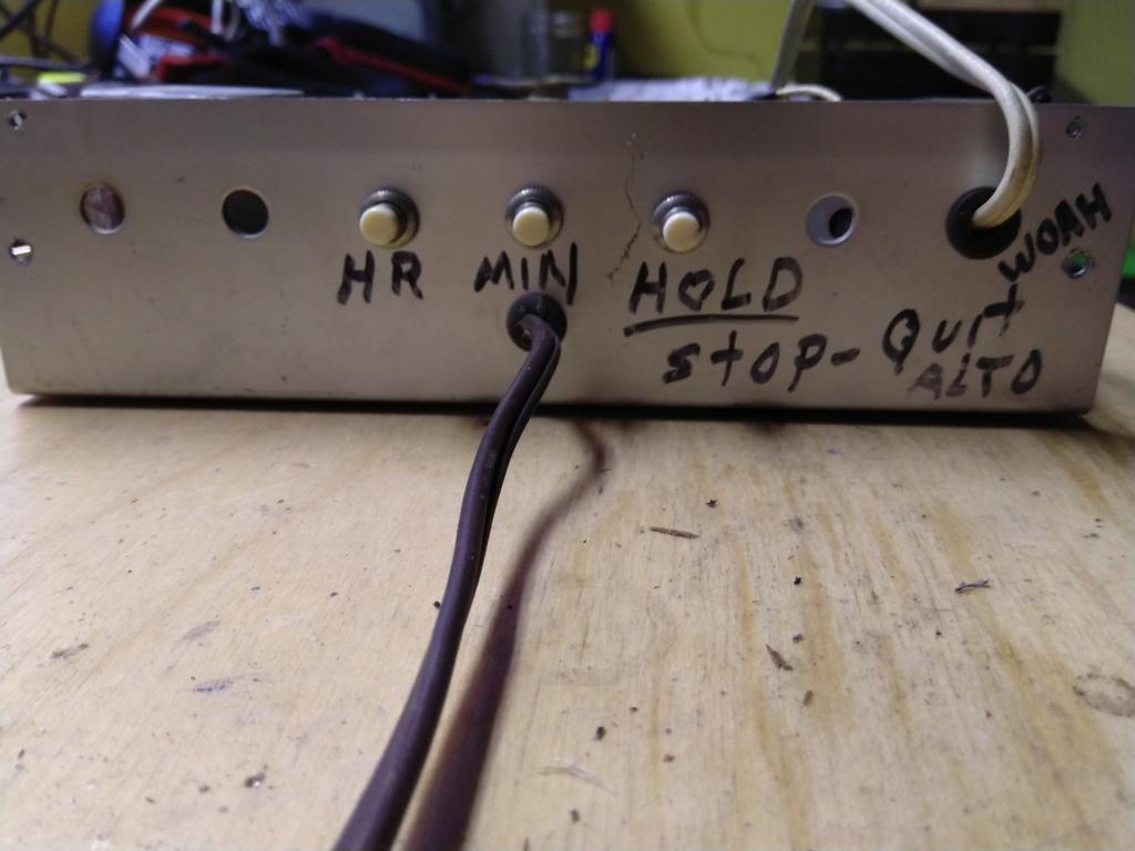
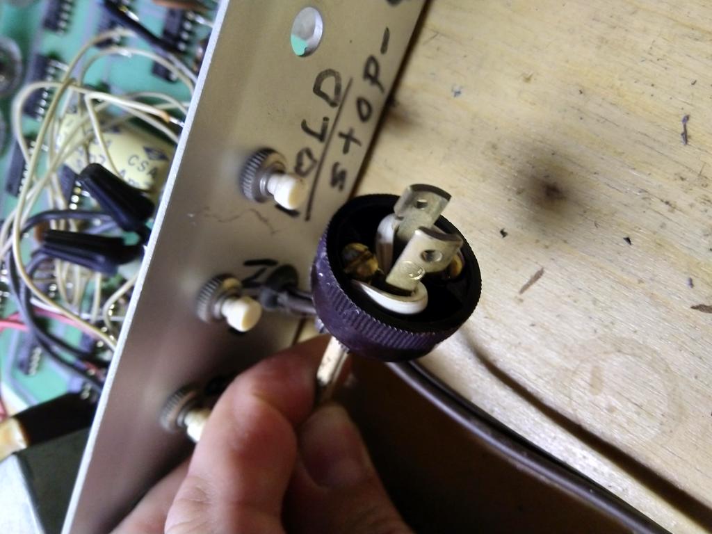
I immediately noticed that this thing had two power-type cords coming out the back. One was a normal 2-prong 110V plug, but the other was some sort of odd twist-lock plug. I took it home, plugged it in, and noted that while it would display a time, the time did not advance, and the buttons labeled “hold” and “min” did nothing, while the “hr” button simply made the time move forward rapidly when pressed. Opening it up, I found that both cords were connected to transformers, but that the twist-lock cord’s transformer outputs looked a little more ad-hoc, being just soldered to a resistor’s leg (and the ground plane) rather than going into its own through-hole. I had other stuff to do, though, so I put it on the shelf and left it alone for a while.

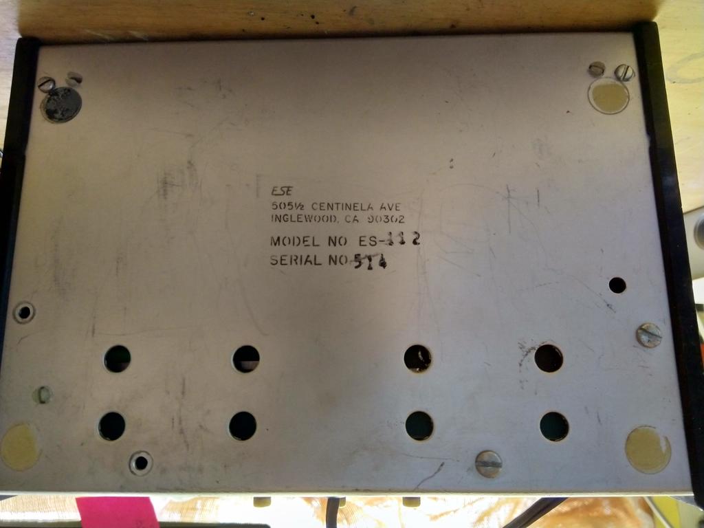
Yesterday, I finally got around to playing with it again. It is stamped “Model No ES-112” and “ESE” on the bottom; with minimal searching I was able to find out that a company named ESE (possibly El Segundo Electronics?) had offered this as a kit back in the 70s. Luckily, the company still exists, and their website got me in contact with an enthusiastic employee who sent me a PDF scan of the manual and informed me that the serial number 514 meant it had shipped the 14th week of 1975.
Because this clock was made in the 70s, the manual included wonderful schematics and board layout diagrams. I quickly determined the twist-lock plug & associated transformer were not marked in any of the schematics or mentioned as an option. I also saw that the 60Hz timing signal should be “visible” at the junction of R1, R2, and C2 in the diagram below, but attaching the oscilloscope (another flea market find, $12) showed nothing there.
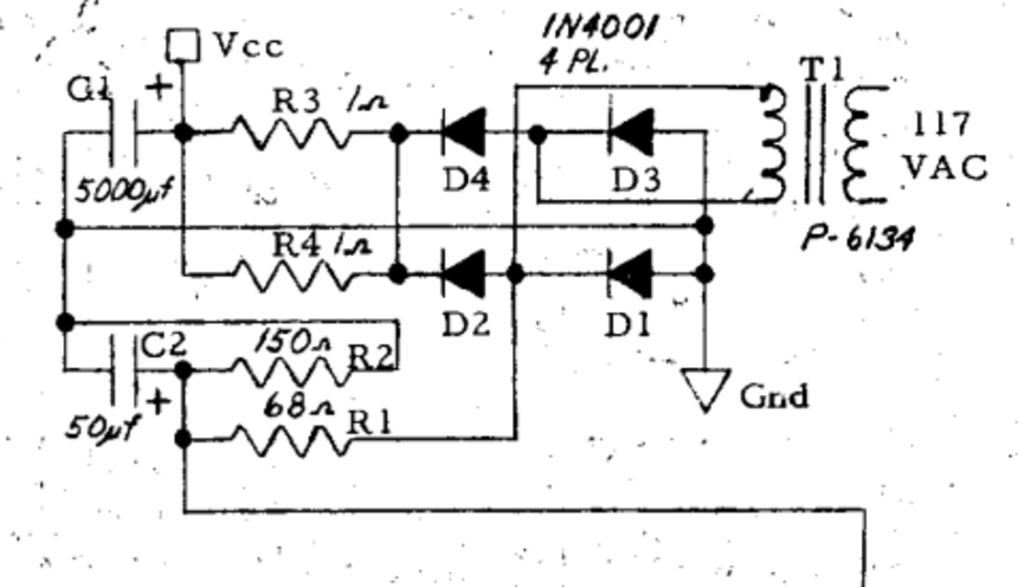
To be safe, I replaced C1 and C2, which were both electrolytics and thus prone to failure, but saw the same behavior.
Finally, after crawling over the board, I found what I should have realized a long time ago: there was a cut trace between diodes D1/D2 and the resistor R1. Rather than connecting to those rectifier diodes, R1 had been connected to one of the outputs of the second transformer, the one with the strange twist-lock plug. I assume the users applied their own A/C signal to this second plug, which was transformed down to a more suitable voltage and applied through R1. I am not sure exactly why they did this, except perhaps to use a higher or lower frequency to run the clock faster or slower than real time.
(Note that this circuit board was all browned and nasty-looking like this when I opened it up… I assume it’s from years of heat coming off the transformer. I decided to just leave it.)
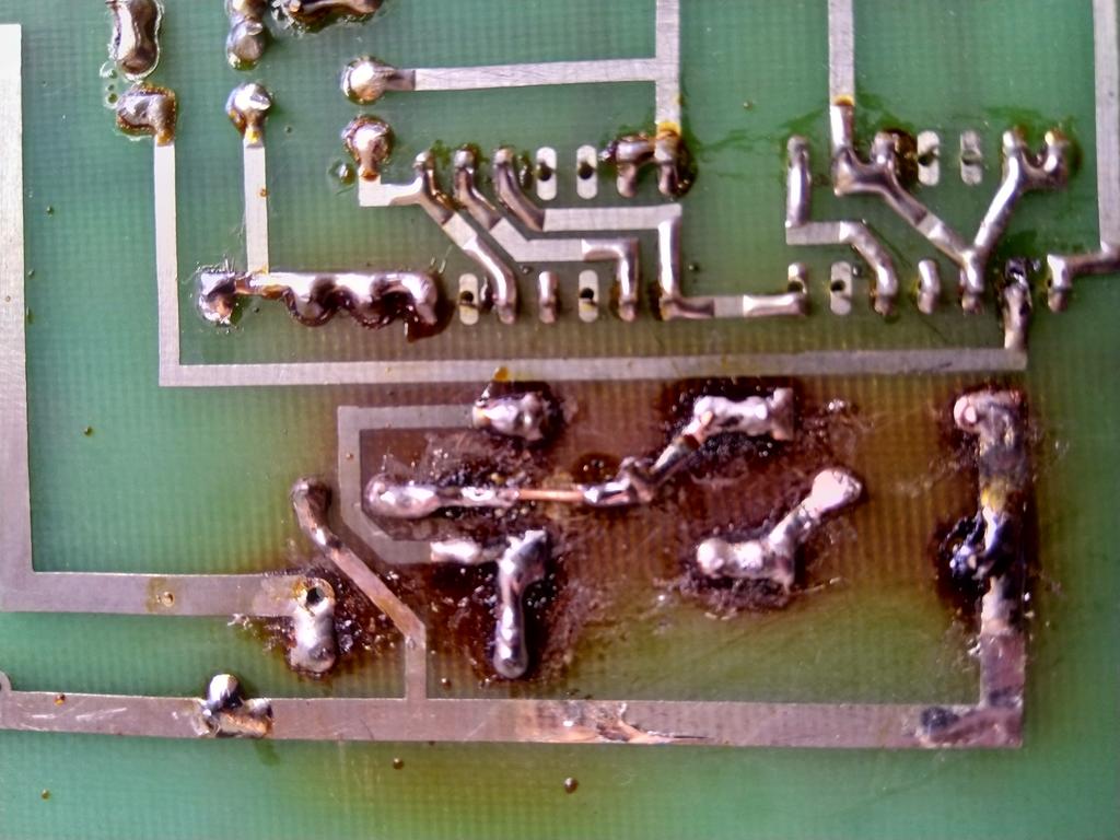
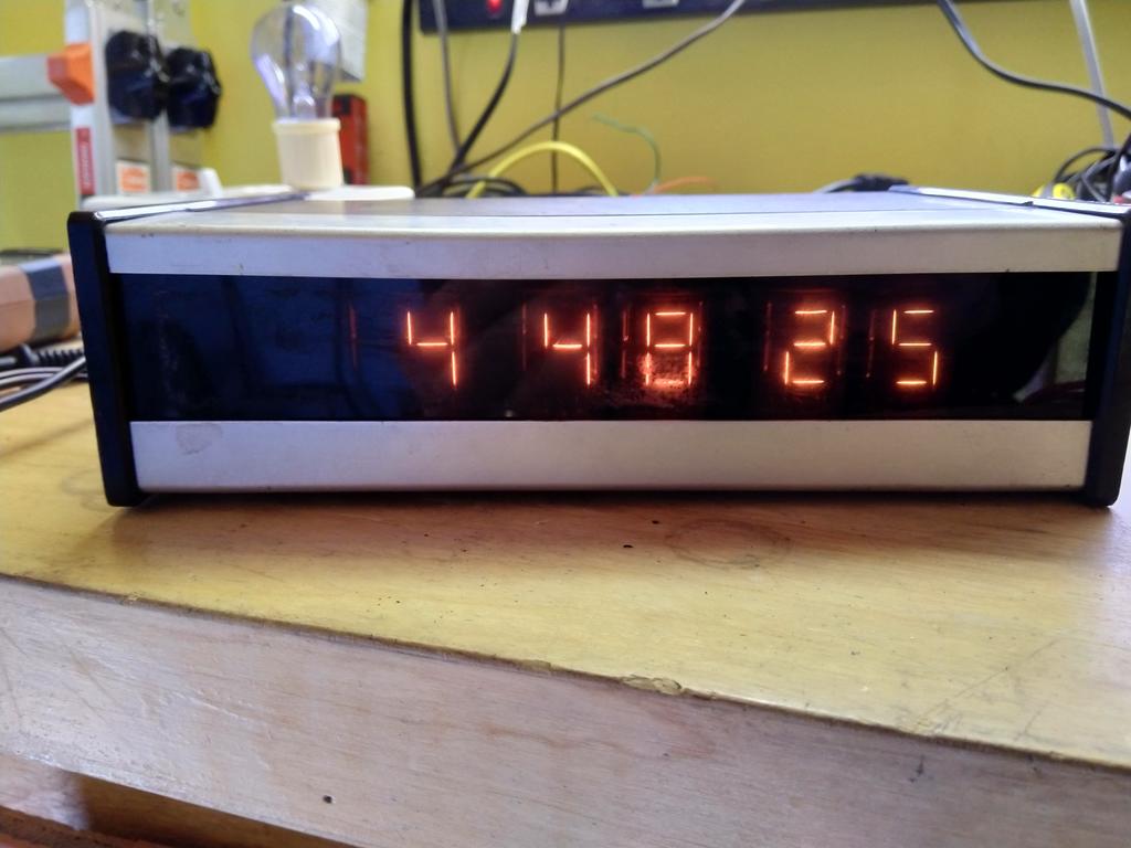
In any case, I soldered a snip of wire across the cut trace and the clock operated normally! I buttoned the case back up, leaving out the secondary transformer and its cord. I now have an attractive timepiece from 1975, suitable for use with any turntables or tube-powered ham radio equipment.