Posted 2022/3/2
The Bellwether Mouse: A Modern Depraz Clone
Want to build your own? You can find 3d models, the PCB, and the firmware here.
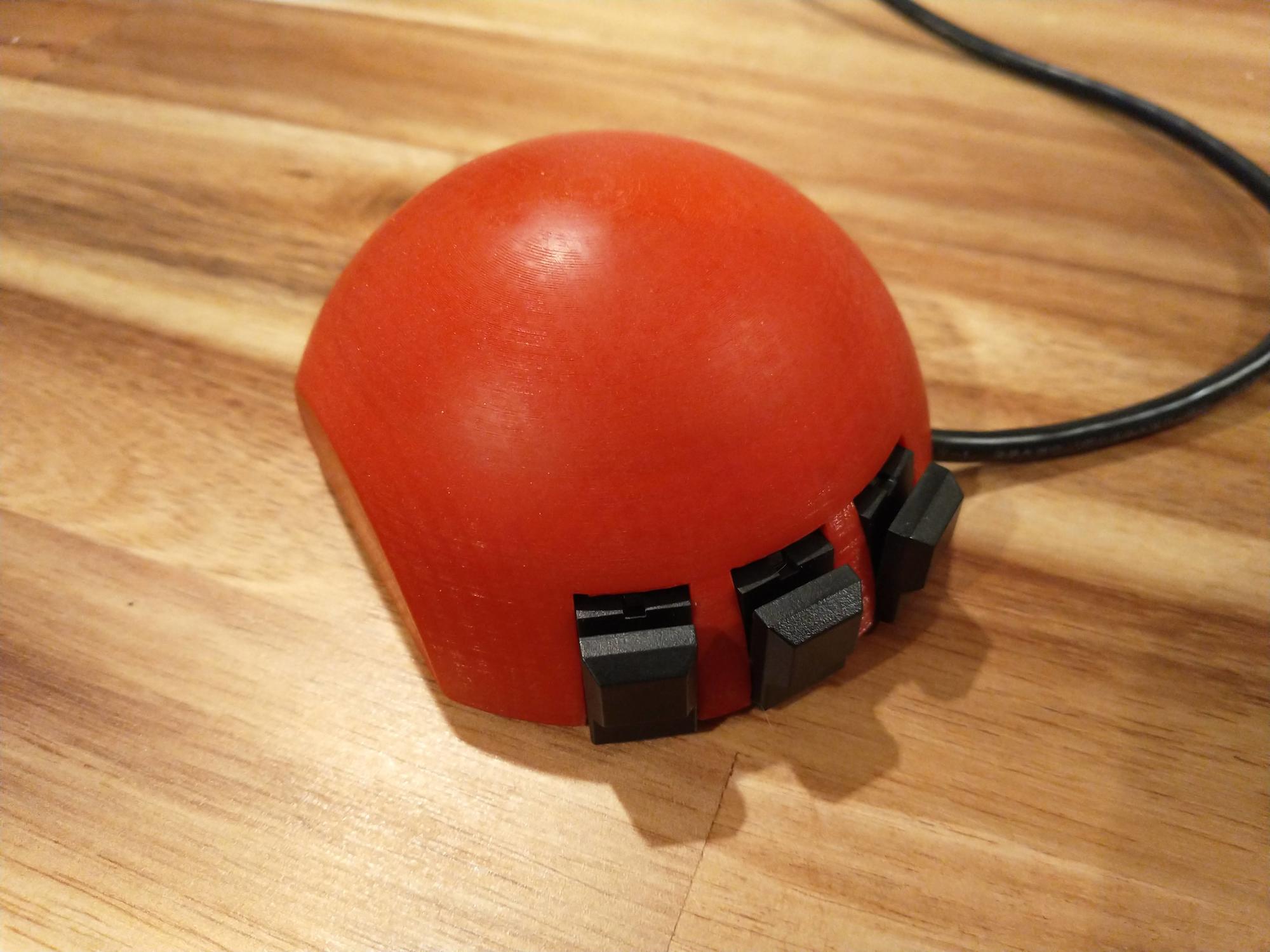
Bellwether is a modernized reproduction of the classic Depraz mouse. From the outside, it looks much the same: classic half-dome design, same 3 buttons, no scroll wheel, cord coming out of the same corner. Inside, though, it features a high-end Pixart PMW3389 sensor and a PIC16F1454 microcontroller–and of course, it’s connected via USB rather than the original raw quadrature encoder output.
I started designing Bellwether after building an adapter for the original mouse & finding it underwhelming on a modern computer–specifically, it’s not nearly smooth or precise enough on a high-resolution screen. I thought that designing a “clone” entirely from scratch would be a fun experience and would let me–and maybe others–experience the Depraz-style mouse with all the modern conveniences.
Body Design
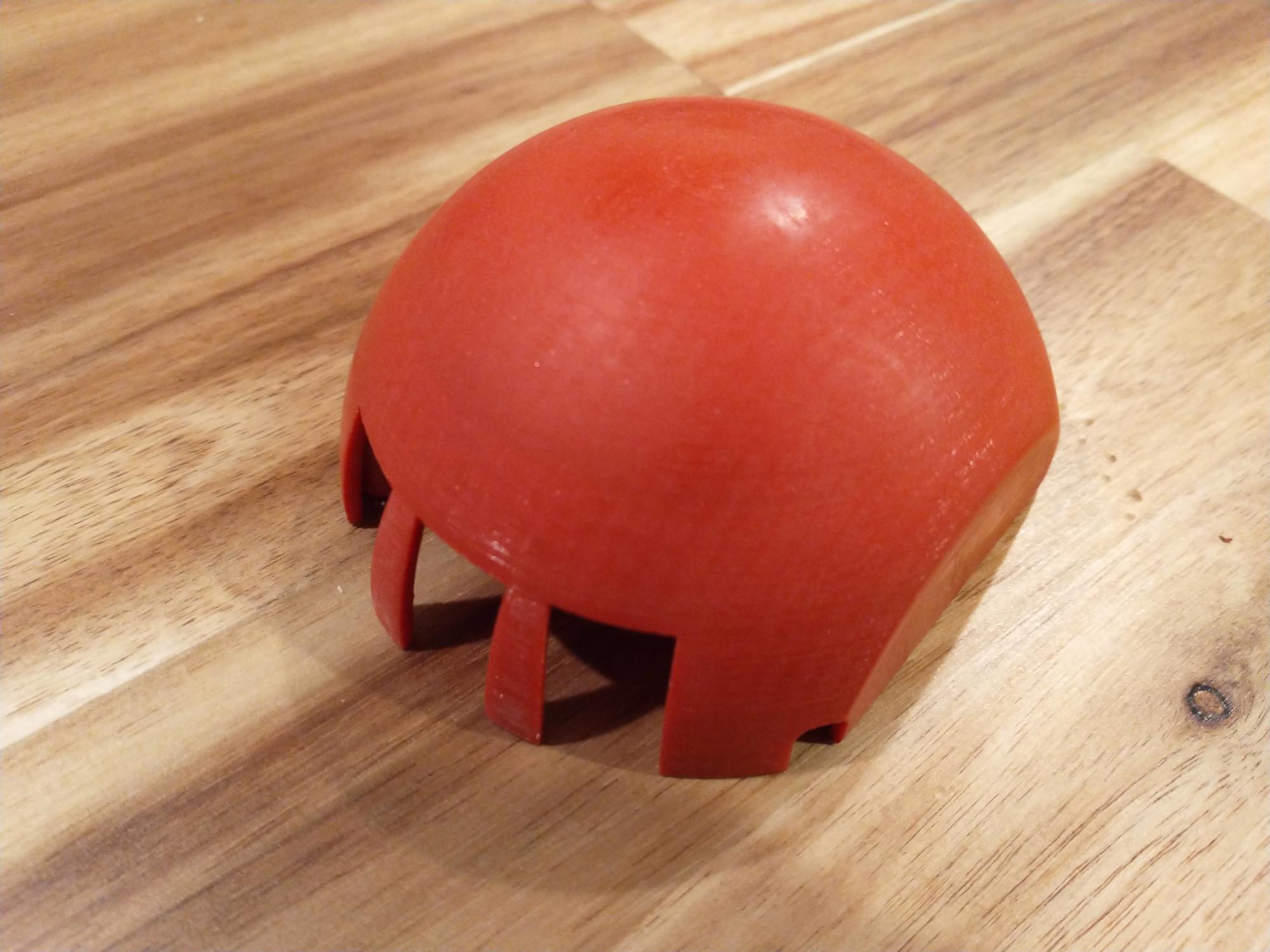
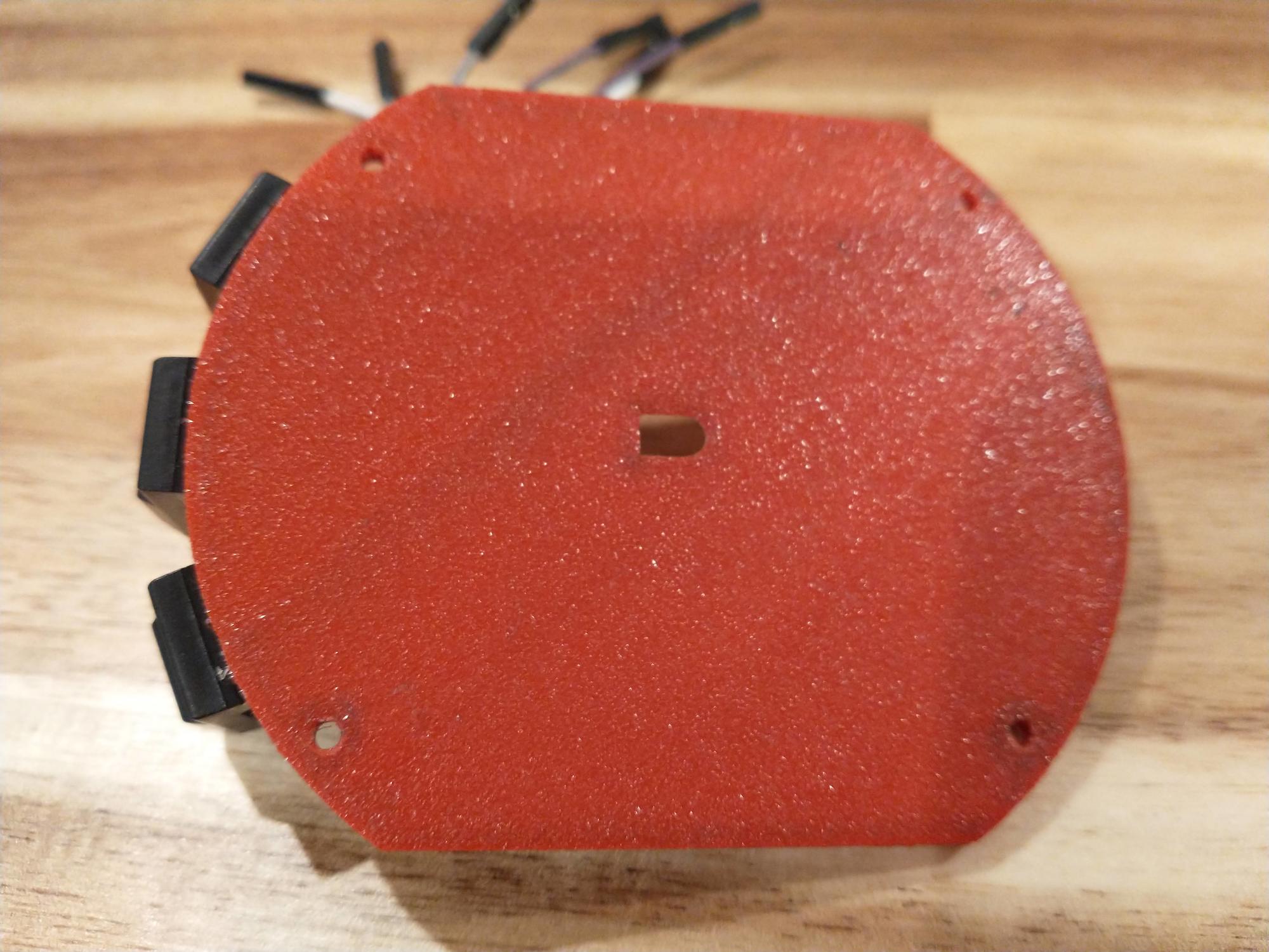
I designed the body first in FreeCAD, working off measurements taken from the original mouse. I had to learn FreeCAD to do it, but it’s a nice piece of software and didn’t take too long to get spun up–although I’m sure my design process was sub-optimal in many ways! The hemispheric top of mouse is very similar to the original, indeed it fits onto the original mouse body just fine.
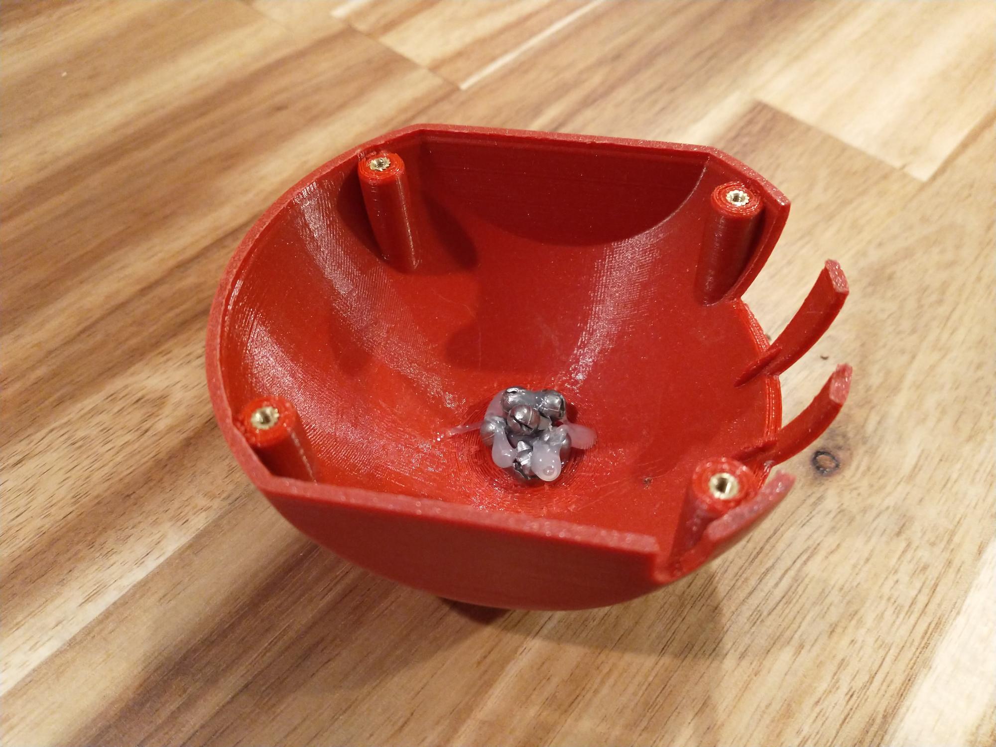
I glued in some lead fishing weights to give it more heft, in a bit of a nod to my original Depraz’s lead champagne foils. Without added weight, the assembled mouse is almost comically light.
The design differs significantly, however, when it comes to the base. The original mouse has a steel ball, with the main PCB mounted above the ball. A flexible PCB holding the buttons is soldered to the curved front of the main PCB. Because I would be using a laser sensor, I knew my PCB would be mounted much lower, meaning I couldn’t really duplicate the flexible PCB button mount. Instead, I put three shallow slots on the front of the base where I would glue the mouse buttons. A small post at the back of each slot helps position the buttons correctly.
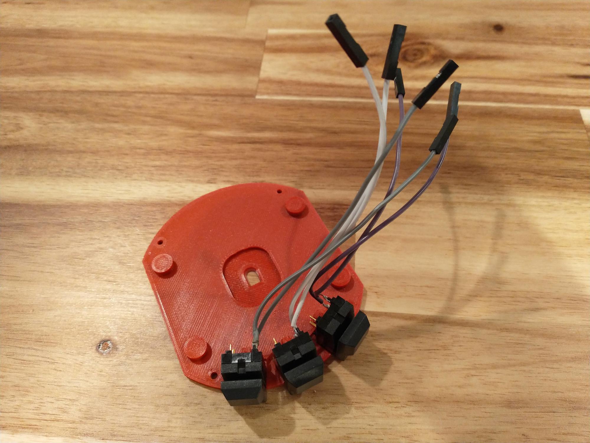
The switches were a challenge to track down; I ended up going with DigiKey part #EG1701-ND, a “Pushbutton Switch SPDT Keyswitch Through Hole” manufactured by E-Switch.
Circuit Design
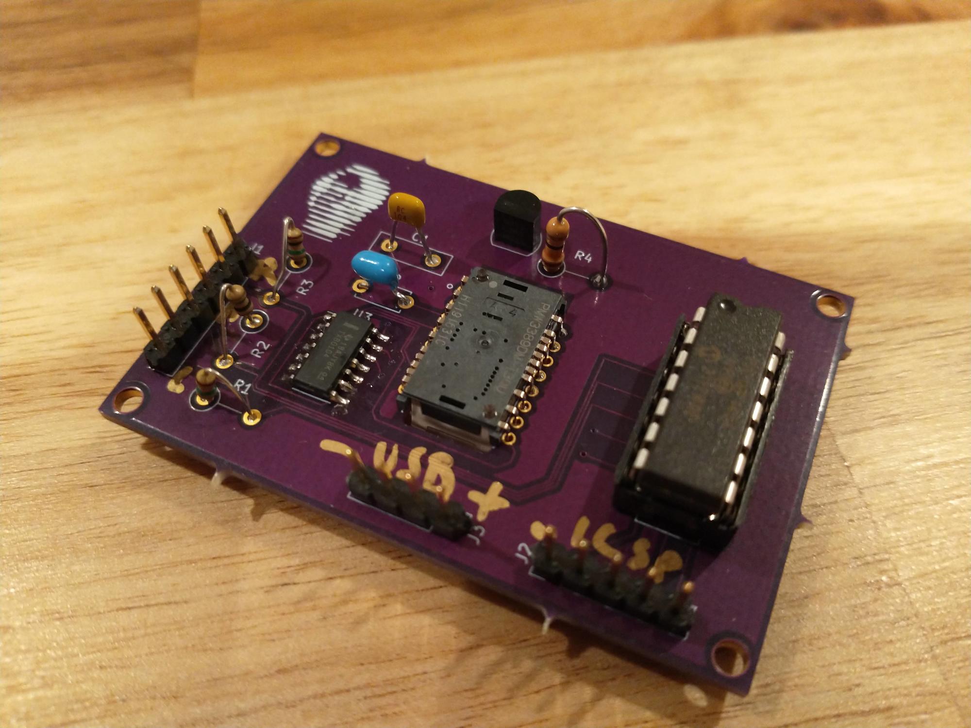
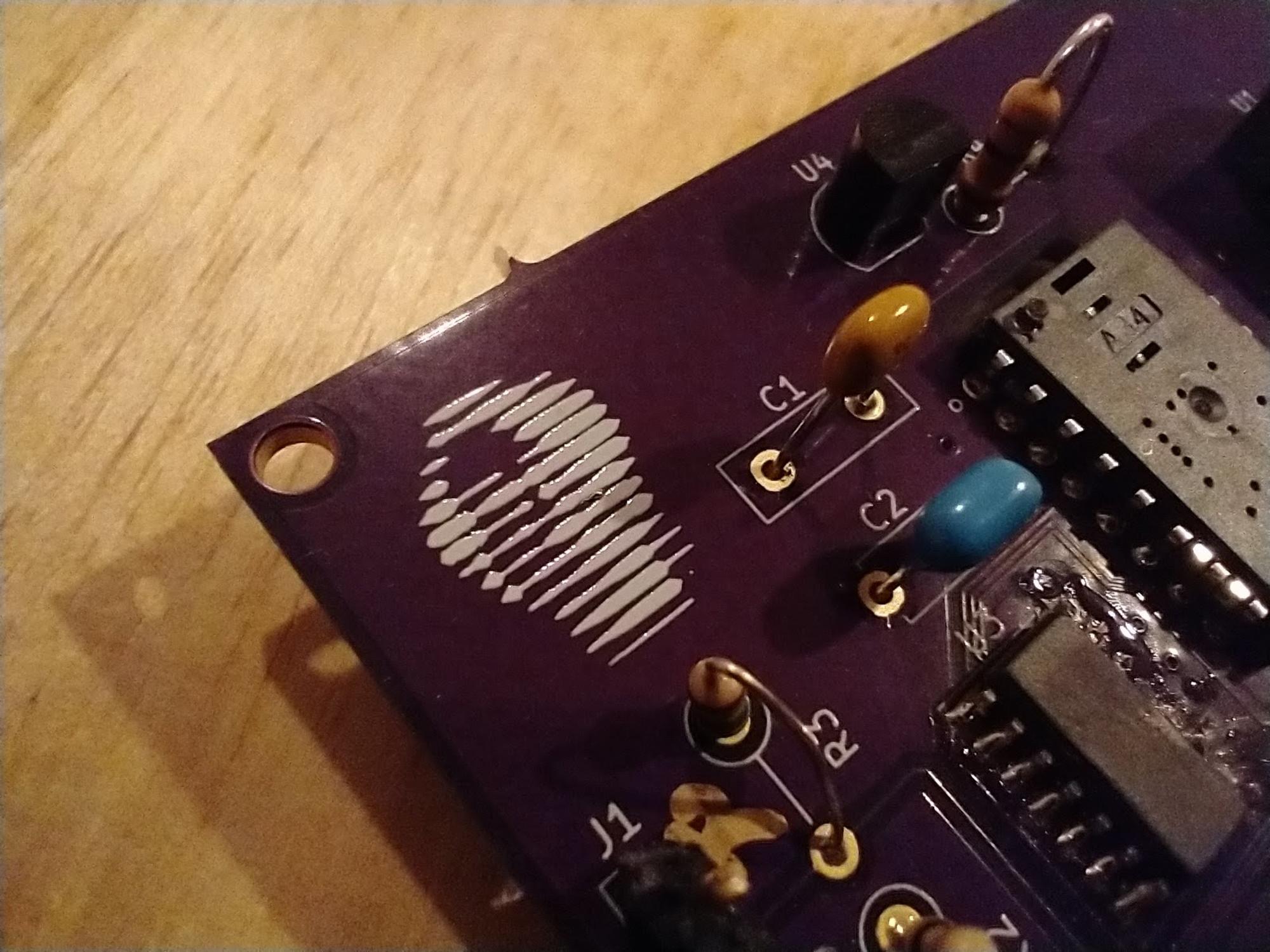
The circuit was designed in KiCAD. It is pretty simple, basically just wiring up the SPI lines of the sensor to the PIC and hooking up the switches. The most complicated part was dealing with voltage levels; the PMW3389 wants to operate at about 2V, while the PIC really needs to be higher. I ended up running the PIC at the USB 5V level, then using a Low-Dropout Regulator (DigiKey part #1662-1933-ND) to drop 5V down to 2V for the sensor and using a pair of TXB0104D level shifters to change signal levels between the PIC and the sensor.
Note that all components except the TXB0104D shifters are through-hole mount. I had initially intended to use 100% through-hole components, because while I personally don’t mind SMD, many people find it intimidating or hard to work with. However, as I tried to tackle the problem of interfacing the 2V sensor to the 5V PIC, sketching out plans that would involve many discrete MOSFETs and other components, I eventually decided that the SMD level shifters were too perfect a solution to ignore.
Board Design
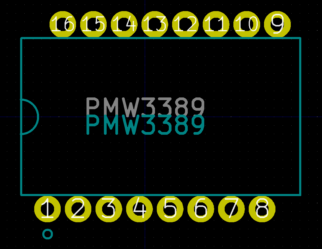
The board was also laid out in KiCAD. I had to design a custom footprint for the PMW3389 sensor using measurements given in the datasheet, because it uses an unusual pin layout; rather than a traditional 16-pin DIP footprint where pin 1 is directly across from pin 9, pin 2 is across from pin 10, and so on, the pins are instead offset from each other as seen below. You can download the footprint for this device here.
With the custom footprint designed, layout was largely a matter of positioning the sensor in the exact center of the board and then arranging everything else around it in a semi-sensible fashion. The biggest complication in this process is that the mouse sensor requires a cutout underneath it, so I was not able to route anything through the center of the board. After getting everything laid out, I found that I had a pretty big empty space in one corner, so I put a picture of PJW’s face on the mask in that corner.
Assembly & Programming
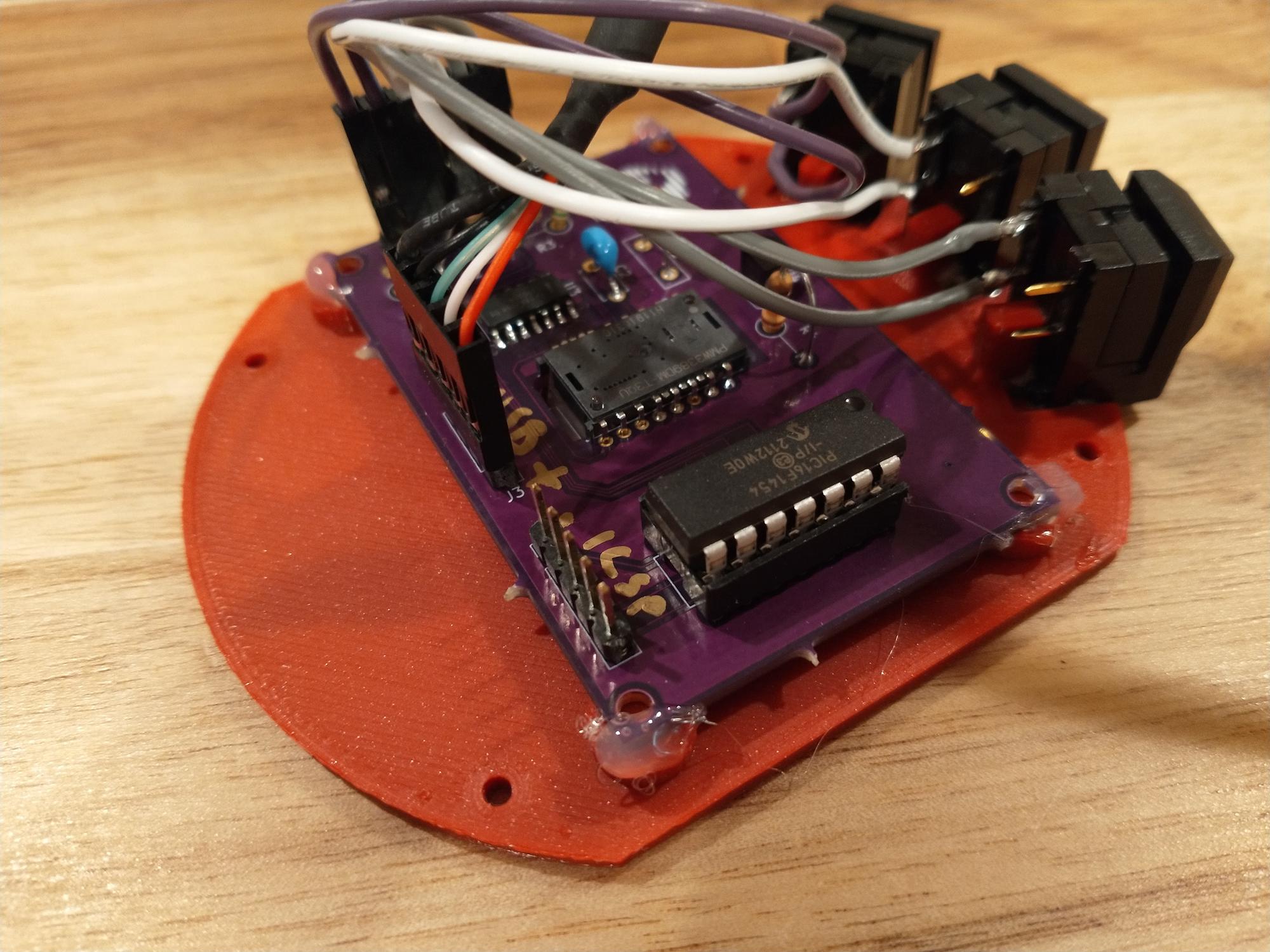
I got a batch of three boards made by OSH Park for $18, including shipping. I was able to order all electronic components from DigiKey, except for the mouse sensors which I had to get from AliExpress–unfortunately it seems that PixArt are not interested in selling sensors directly to hobbyists. Assembly consists of:
- Populating the PCB
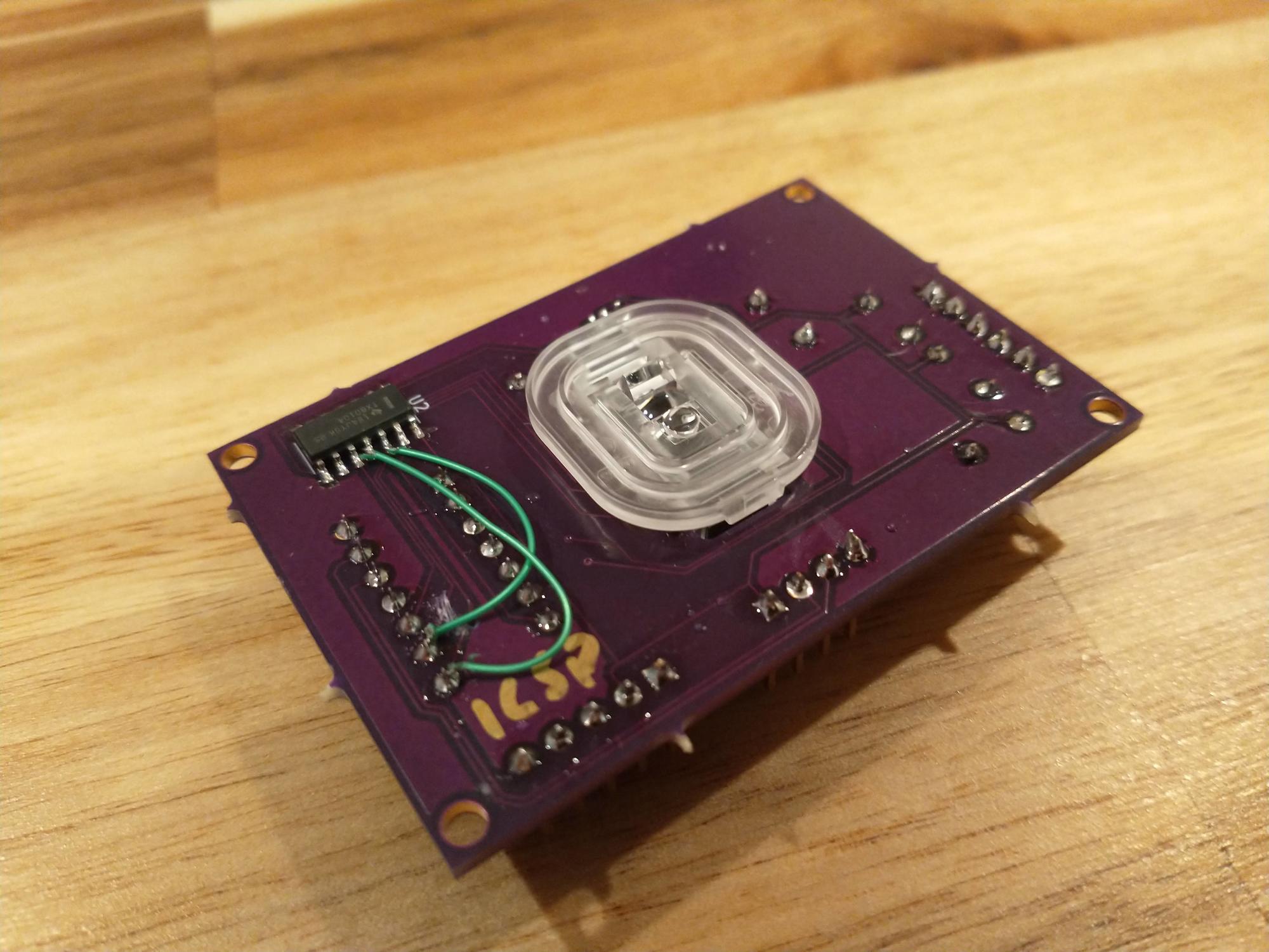
- Fitting the lens onto the mouse sensor (it’s a press-fit)
- Gluing the switches onto the base & clamping them down until cured
- Soldering leads onto the switch terminals
- Setting the PCB onto the base and hot-gluing it down (I designed it to be screwed down, but I find hot gluing easier than dealing with heatserts so far)
- Plugging in the switches and the USB cable
The firmware is based on Microchip’s USB HID demo code (which just moves the cursor in a square on the screen) and Daniel Kao’s Arduino code which he used to put the PMW3389 into a Kensington Expert Mouse trackball. Specifically, I started with the Microchip demo code, then referred to Daniel’s code to figure out how to properly talk with the sensor.
In the software development phase I discovered that I had the SPI connections on the PCB backwards; there are too many terms for the 4 SPI lines (MOSI, MISO, SDI, SDO, SDA, DIN, DOUT…) and I basically connected the PIC’s input line to the sensor’s input line, and the PIC’s output line to the sensor’s output line. I’ve had to cut the traces and solder in jumpers on the two boards I’ve assembled so far.
The Finished Product
The mouse works well enough at this point for daily use. The cursor movement is very smooth and the buttons have a satisfying click.
TODOs and Open Questions
If I make more mice, I’ll need to update the PCBs a little to fix the SPI problem and to add mask annotations for the various pin headers (it’s kind of challenging to figure out where each button connects, for instance).
I’m also still not 100% convinced that the switch mounting solution I came up with is ideal. For starters, it means that changing a failed switch would be challenging, or may even require an entirely new base plate + three replacement switches. However, it’s very convenient, easy to assemble, and has so far stood up quite well to regular use.
I need to find a source for nice flexible USB cables, ideally with that soft braided covering.
Finally, I need to decide if I’m going to release the 3D models & PCB layouts to the world, or if I should attempt to produce these mice for sale. I’m not 100% sure I want to get into the artisanal hand-crafted mouse business, but if enough people are interested and are willing to pay enough to make it worthwhile, I may produce a few batches for sale. In that case, I’d need to look into injection molding, a whole new realm in which I have zero experience!
Conclusion
This project has been a lot of fun. I haven’t really done this sort of circuit design and PCB layout since college, and I truly enjoyed getting to brush up my skills (after my initial dismay at learning EagleCAD is no longer the de facto standard). Any suggestions or comments are welcome; you can find my contact information on my home page.